Naboo - Gas Heating System
Components
Plug-In Gas
The gas plug-in board, plugged on the relays board, acts as an interface to the blower and ignition panel and can hold one chamber burner and one boiler burner. In floor units, the second plug-in is required.
The gas system is based on:
Ignition panel
The ignition panel LA63060170, common to all burners and models, controls the burner group and brings back to the gas plug-in the operation of the burner.
The panel is fixed to the valve by a screw that also holds in place the lid that protects their electrical connections.
Warning: To grant flame recognition it is needed that the voltage between N and earth is 0V and in any case that it is lower than the one detected between Phase and Ground.
Gas valve
|
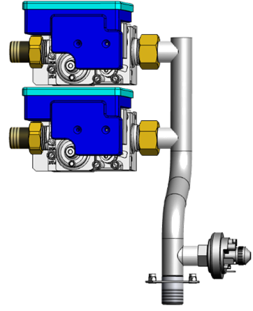
The gas valve, common to allburners and models, is a pre-calibrated 0 offset valve, so adjustments are notallowed,
it is important to use only original and genuine spare parts.
The valve is connected inbound to the gas ramp and outbound to the blower/venturi group through a flexible pipe which on its end house the gas nozzle.
|
 |
|
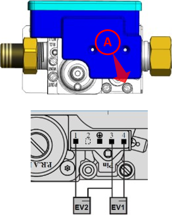
On the valve there is a screw A) that allows you to detect the input pressure. Always measure the input pressure in both static and dynamic conditions.
To verify the correct function it is possible to check the continuity of the windings of the solenoidvalve. To check them disconnect the ignition panel from the valve and check directly on the pins as shown.
|
 |
Gas Nozzles
|
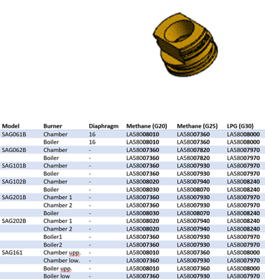
The nozzle is used to enter an exact amount of gas, necessary to develop the power required to the burner, and allows a simple and error-proof gas conversion without any mechanical adjustment.
It is essential to install the nozzle suitable for the model, burner and type of gas, see table; the nozzles are marked with the last 5 digits of the code.
In 061 models there is also a diaphragm at the outlet of the blower
|
 |
Mixer - venturi
|
The nozzle is used to enter an exact amount of gas, necessary to develop the power required to the burner, and allows a simple and error-proof gas conversion without any mechanical adjustment.
It is essential to install the nozzle suitable for the model, burner and type of gas, see table; the nozzles are marked with the last 5 digits of the code.
In 061 models there is also a diaphragm at the outlet of the blower
|
 |
Blower
|
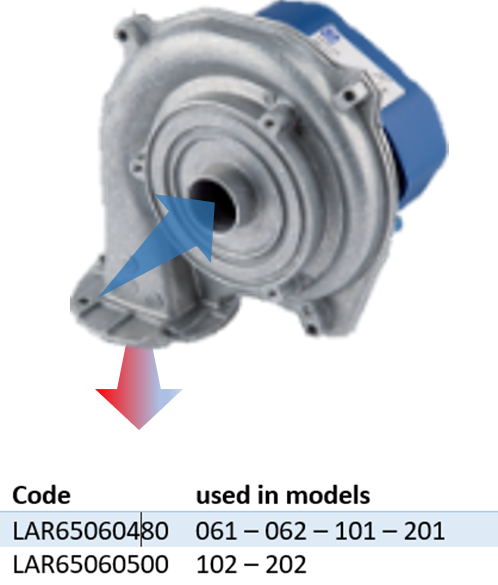
The blower sucks through the mixer the air and, through the nozzle of the valve, the gas and compresses the mixture into the burner head.
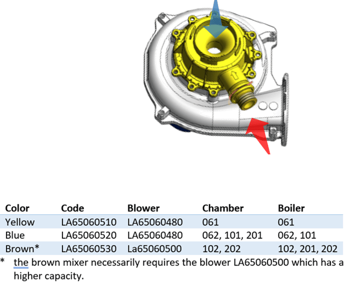
There are 2 blowers that differ in the internal fan
Warning: It is essential, in case of replacement, to verify that the connections are tight and that the mixer has been installed in the same position as the original one because the spaces and dimensions of the components do not allow different assemblies:
|
 |
Burner head
|
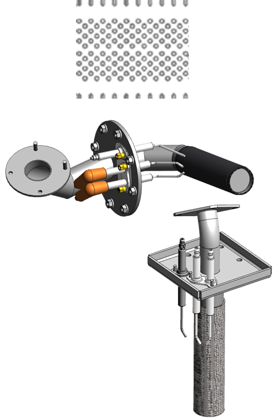
The mixture is pushed by the blower into the burner head. It is a tube with a dense puncture covered with a dense metal mesh that helps to spread the mixture and to have a diffuse and uniform flame.
The integrity of the net and surface of the burner is fundamental for the proper functioning of the burner.
|
 |
Ignition transformer
|
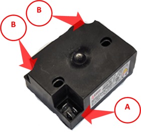
The ignition transformer LA65180260, common to all burners of all models, ensures better ignition and converts the ignition signal 230V of the ignition panel into a 20KV signal.
The transformer has double output, the ignition voltage is between the two outputs and not towards mass, so that the spark always come between the two electrodes and not towards mass. Also, given the high voltage, the spark is guaranteed even if the electrodes should diverge.
A)In power 230V
B)Out high voltage
|
 |
Electrodes
|
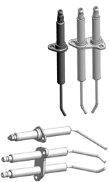
The burner needs:
Twin ignition electrodes, among which the spark that triggers the flame is released.
These electrodes are mechanically coupled and are supplied already bent to ensure quick replacement and are easily distinguishable because they carry high voltage cables.
A detection electrode that detects the flame current, a current that is generated thanks to the state of ionization of gases in the flame.
|
 |
Mandatory activities on gas units
On Gas units, for safety and reliability reasons, some activities are absolutely needed during installation, inspection and yearly inspections.
Refer to maintenance section for details
|
|
Always check if the gas type reported on the plate has corrispondence with the type of gas supplied
|
|
Always inspect the supply line for leakages, at least from the tap.
Inspect both outside and inside on each connection.
An electronic detector is strongly recommended, NEVER use flames to search leakages.
|
- Gas pressure measurement Static and Dynamic
|
Always measure the gas pressure supply!
Pressure for gas is same as current (A) for electricity.
Check the static pressure, means wile unit is off, but most important check the dynamic pressure, means while unit is absorbing the max power.
If possible turn on all gas appliances in order to check if plant grant the max load.
|
- Flue gas analysis per each burner
|
When installing, after modifications/repairs and yearly check combustion with a flue gas analysis.
CO2 must be in the range.
Most importante CO must be as low as possible, anyway below 300ppm.
|
- Electrodes deformation inspection
|
Inspect yearly ignition and detection electrodes simply comparing the one installed with a new one you take with you.
|
GAS HEATING SYSTEM
When the relays board receives the signal to start the heating, it sends a signal to the gas plug-in.
Sequenza di accensione
The gas plug-in send a signal to the blower to start spinning
The blower, always powered, start to spin according to the control frequency.
When the blower rotates it sends a signal back to the gas plug-in
After a specific time the system begins to monitor the return frequency.
The relays board continues to monitor the correspondence between the required rotation regime and the actual rotation.
The ignition panel is activated and powers the ignition transformer, which generates a spark between the ignition electrodes. At the same time athe gas valve is activated.
The gas valve releases into the venturi duct a quantity of gas determined by the nozzle, which is installed on the venturi. The depression in the Venturi is generated by the blower rotation.
The gas mixed with air is pushed into the duct leading to the burner's head and here it is ignited by the ignition spark between the 2 ignition electrodes
If the mixture ignites and the flame does not leave the surface, the detection electrode allows the ignition panel to sense an ionization current.
The panel will send a signal to the plug-in and the system will go to the necessary speed (between min and max).
If the flame is not detected within a certain time the system will stop the sequence, blow out all the air from the heat exchanger and restart the sequence automatically.
This will happen max 3 time; at the third attempt the ignition panel will send an alarm to the control board (A21, 23, 25, 27).
Pressing on the display to reset the alarm will restart the ignition sequence.
When the heating request stops, the system turns off the ignition panel, that closes the valve, and the blower is stopped.
Gas System NABOO
Request to heat
The ignition starts with a request from the main board to the plug-in gas.
The request specify the power requested through the PID system
GAS SYSTEM MANAGEMENT NABOO
|
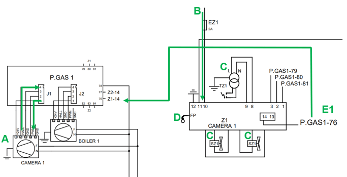
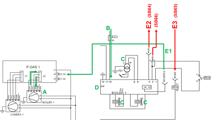
A) Blower start-up
As first action the plug-in activate the blower through a signal in frequency The frequency define the blower. RPM.
The blower generate a signal to inform the plug-in about his real speed.
If speed is not reached in a certain time A20 will be generated (A20, 22, 24, 26)
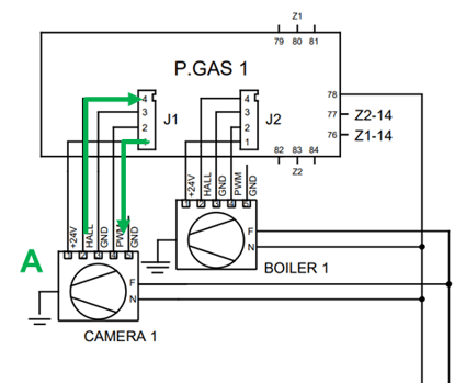
|
|
B) Ignition sequence
When blower reaches the right speed the main board will activate the ignition panel with a 230V signal through fuse EZ1 to protect the panel.
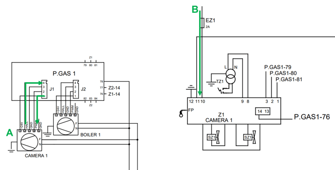
|
|
C) Ignition
Sequence continue activating the HV transformer to generate the spark on electrodes and powering the gas valve solenoids.
Gas will flow into the burner depending on the nozzle and on depression generated from the air flow into the venturi.
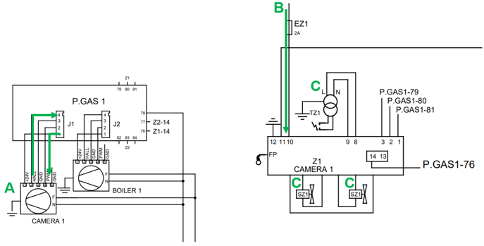
|
|
D) Flame detection
If ignition is successful a current will be detected through the detection electrode.
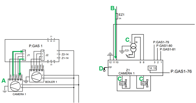
|
|
E1) Flame detected
If flame is detected the ignition panel send a signal from pin 14 to plug-in 76 and the blower will be switched to the RPM defined by the PID
|
|
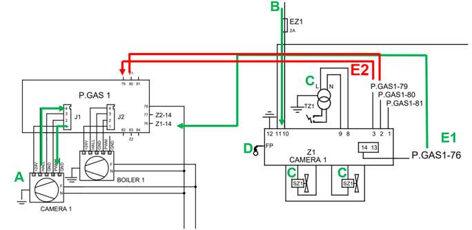
E2) No flame detected
If flame is not detected for 3 times the system send an alarm signal to the plug-in to inform about unsuccessful ignition.
Signal from ignition panel pin 3 to plug-in 79 and unit will show A21
|
|
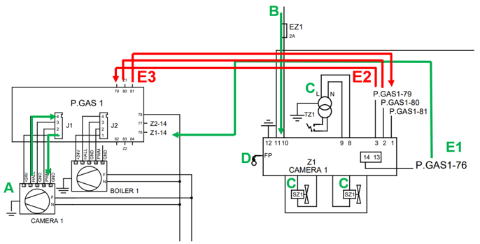
E3) Restart ignition
If the customer selects the button on display to restart the sequence plug-in will send a restart signal 81 to the panel 1 closing the circuit 80-81 to make a short on ignition panel 1-2
|
|
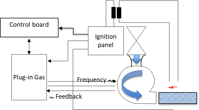
On Sapiens units the gas system is similar but different.
Plug-in gas only control the blower speed and receive the flame detected signal.
Relays board for cabinet and boiler expansion board manage the missing flame / restart signals
|
|


