REQUIREMENTS FOR GAS TYPE AND GAS PRESSURE
Check that the factory gas setting on the appliance corresponds to the effective conditions for the gas connection on-site. The set gas type in the appliance and the dynamic connection pressure must coincide with the instructions shown on the data plate.
Static and dynamic pressure must be checked; 10% max permissible difference.
For LPG installations we recommended to add a OPSO (Over-Pressure Shut-Off) device.
LEAK TEST EXCEEDING OF ALLOWED CO/CO2 VALUES
Risk of intoxication if the allowed CO/CO2 values are exceeded due to the incorrect setting of the burner.
- During the first start-up, perform an analysis of the exhaust gas.
- Document the exhaust gas values.
- The exhaust gas analysis must be performed only by a manufacturer’s authorised technician. The exhaust gas analysis must be performed before placement into service.
- The gas connection must be made strictly by a local authorised installer.
- The gas connection piping must satisfy the rated thermal load indicated on the data plate.
- The gas supply and distribution in the appliance must be checked for leaks using a suitable testing tool.
GAS CONNECTION
The section of the gas supply pipe must be chosen according to the type of gas and the consumption of the appliance to be connected. The system must be designed and installed in accordance with current regulations.
The gas connection on the oven is R 1/2” or R 3/4”, and this section must never be reduced.
A fast acting shutoff valve must be installed on the gas inlet line to the oven. The valve must be type test approved in accordance with current regulations.
The connection to the gas main can be permanent or detachable; if flexible metal tube is used, this should be made of a stainless and corrosion resistant material.
If when making the connection you use any sealing materials, they must be type test approved for this purpose.
LEAK TEST
All connections between the mains and the appliance must be tested for leakage. The recommended method is to use a proprietary leak detection spray; alternatively, a non-corrosive foamy liquid of any general description can simply be brushed onto the fittings: whichever method is used, no bubbles should appear.
Never under any circumstances test for gas leaks with a naked flame!
EXHAUSTING FLUE GASES
Model 6 GN 1/1 - 5 x 600 x 400
Since this appliance due to its capacity has installation type A3, it is not necessary to connect it to a stack for extracting the flue gases. The flue gases can be exhausted into the installation room. Proper and continuous aeration is essential!
Remaining models
As these ovens have a power rating of
>14 kW, type B installation is required. The installer must select one of the methods described below, according to the design of the building and of the room where the appliance is sited. The diameter of the flue pipes must be as indicated in the installation diagrams.
Warning: flue gases may reach temperatures of 400°C!
Fumes must never be ducted away utilizing an extraction system!
Clear the gas supply system of any machining debris before connecting the oven!
For UK market can be used when replacing similar equipment in kitchens where installation of the air inlet/extraction was prior to September 2001 & providing there is a documented risk assessment to ensure that there will always be sufficient make-up air and extraction available when running the equipment. Please observe Current Gas Regulations (BS 6173). Advised B23 installation due to interlocking regulations.
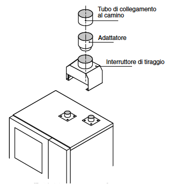
Installation type B13
Extraction with natural draught fitted with a damper and a heat-resistant pipe (see “Flue gas temperatures” in Table 4 under the heading “Technical Data”) connected to the stack. Selecting this type of installation the oven must be fitted with a damper that is specific for each oven (as shown in the drawing). If the oven is equipped with an adaptor collar for standard size flue pipes, fit the adaptor.
Never under any circumstances must flue gases be ducted away directly utilizing a mechanical extraction system.

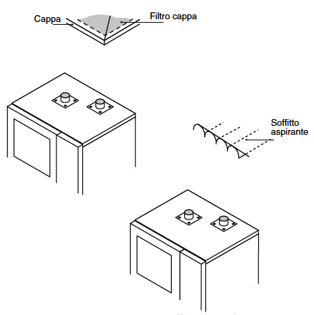
Installation type B23
Flue gases are exhausted mechanically through a suction hood with a heat-resistant filter or a ducted ceiling, without a damper being fitted, and eitherconveyed into a stack or released directly to the atmosphere together with other fumes extracted from the room. Leave a suitable distance between the oven’s smoke outlet and the hood filter or the top intake. Where extraction systems are selected for type B23 installations, these must be properly sized and specified with at least one interlock device that will shut off the gas supply to the oven automatically in the event of the extractor system failing to operate.

After installation, the installer must update the data plate by ticking the box, corresponding to the type of installation made, with an indelible marker pen.
![]()
The manufacturer accepts no liability for any damage or malfunctioning of the appliance attributable to the absence or inadequacy of earthing systems, to the incorrect arrangement or installation of auxiliary systems, also to incorrectly made connections or to non-compliance of the building’s electrical system with current regulations.
